

Klargester Separator Range
In accordance with the Environment Agency guidelines a separator is required where there is a danger of contaminants such as oil and petrol entering a drainage system. The type of system required depends on the level of risk of pollutants entering the drainage system.

The chart below gives guidance to aid selection of the appropriate type of fuel/oil separator for use in surface water drainage systems which discharge into rivers and soakaways.
Owls Hall has a specialist team who provide technical assistance in selecting the appropriate separator for your application.
For temporary storage solutions click here.
To find the correct separator for your needs please follow the Separator Selection Flow Chart.
Separator Selection Flow Chart
The above information was kindly provided by the Environment Agency.
http://publications.environment-agency.gov.uk/pdf/PMHO0406BIYL-e-e.pdf
- You must seek prior permission from your local sewer provider before you decide which separator to install and before you make any discharge.
- We suggest you consult with us prior to ordering the unit to confirm its suitability.
- In this case, if it is considered that there is a low risk of pollution a source control SUDS scheme may be appropriate.
- In certain circumstances, the sewer provider may require a Class 1 separator for discharges to sewer to prevent explosive atmospheres from being generated.
- Drainage from higher risk areas such as vehicle maintenance yards and goods vehicle parking areas should be connected to foul sewer in preference to surface water.
- In certain circumstances, a separator may be one of the devices used in the SUDS scheme. Ask us for advice. Contact us for advice.
This chart gives guidance to aid selection of the appropriate type of oil separator for use in surface water drainage systems which discharge into rivers and soakaways.
For further detailed information, please consult the Environment Agency’s Pollution Prevention Guideline No. 3. (PPG 3), which clarifies the ‘Use and design of oil separators in surface water drainage systems.’ The Environment Agency is working with the Scottish Environment Protection Agency (SEPA) and the Environment and Heritage Service in Northern Ireland in order to produce a range of Pollution Prevention Guidance Notes such as Guideline No. 3. (PPG 3).
Owls Hall Environmental’s engineers operate all over mainland Britain and can assist you in the process of choosing and installing your Separator product. Owls Hall also provides you with an after-sales package, consisting of servicing and 24 hour emergency callout should your Separator start having technical difficulties.
Which Separator do I need?
Please click a range below to see its Features and Benefits.
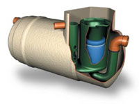
Bypass Separator NSBD Range
Application
Bypass separators are used when it is considered an acceptable risk not to provide full treatment, for very high flows, and are used, for example, where the risk of a large spillage and heavy rainfall occurring at the same time is small, e.g, Surface car parks, Roadways and Lightly contaminated commercial areas.
- Light and easy to install
- Used on low risk sites (Car Parks)
- Sized in litres per second flow
- Independently tested and performance sampled, certified by the BSI
- Available in Class I and Class II formats
- Class 1 designs includes coalescer, treating 10% of flow to achieve a concentration of 5mg/litre of oil
- Class 2 designs to achieve concentration of 100mg/litre of oil
- Inclusive of silt storage volume
- Fitted inlet/outlet connectors
- Vent points within necks
- Extension access shafts for deep inverts
- Maintenance from ground level
What size NSBD Bypass Separator do I need?
To specify a nominal size Klargester Bypass Separator, the following information is needed:
- The calculated flow rate (NS) or the drainage area served. Our designs are based on the assumption that any interconnecting pipework fitted elsewhere on site does not impede flow into or out of the separator
- The required discharge standard. This will decide whether a Class I or Class II unit is required
- The drain invert inlet depth
- Oil alarm system available
- Owls Hall offer a full Installation service. Please visit our Installation section for more information.
- Pipework type, size and orientation
Bypass NSB Table
Sizes & Specifications
| Nominal Size | Flow (l/s) | Peak Flow Rate (l/s) | Drainage Area (m²) PPG3 (0.0018) | Silt Storage Capacity Litres | Oil Storage Capacity Litres | Length | Dia. | Access Shaft Dia. | Base to Inlet | Base to Outlet Invert | Standard Fall Across Unit | Min. Inlet Invert | Standard Pipework Dia. |
|---|---|---|---|---|---|---|---|---|---|---|---|---|---|
| NSB3 | 3 | 30 | 1670 | 300 | 45 | 1765 | 1225 | 600 | 1450 | 1350 | 100 | 500 | 160 |
| NSB4 | 4.5 | 45 | 2500 | 450 | 68 | 1765 | 1225 | 600 | 1450 | 1350 | 100 | 500 | 200 |
| NSB6 | 6 | 60 | 3335 | 600 | 90 | 1765 | 1225 | 750 | 1450 | 1350 | 100 | 500 | 200 |
| NSB8 | 8 | 80 | 4445 | 800 | 120 | 3065 | 1225 | 750 | 1450 | 1350 | 100 | 500 | 225 |
| NSB10 | 10 | 100 | 5560 | 1000 | 150 | 3915 | 1225 | 750 | 1450 | 1350 | 100 | 500 | 300 |
| NSB12 | 12 | 120 | 6670 | 1200 | 180 | 3915 | 1225 | 750 | 1450 | 1350 | 100 | 500 | 300 |
| NSB15 | 15 | 150 | 8335 | 1500 | 225 | 3915 | 1225 | 750 | 1450 | 1350 | 100 | 500 | 300 |
| NSB18 | 18 | 180 | 10000 | 1800 | 270 | 4530 | 1442 | 600 | 1530 | 1430 | 100 | 1000 | 375 |
| NSB24 | 24 | 240 | 13340 | 2400 | 360 | 3200 | 2012 | 600 | 2110 | 2010 | 100 | 1000 | 375 |
| NSB30 | 30 | 300 | 16670 | 3000 | 450 | 3945 | 2012 | 600 | 2110 | 2010 | 100 | 1000 | 450 |
| NSB36 | 36 | 360 | 20000 | 3600 | 540 | 4625 | 2012 | 600 | 2110 | 2010 | 100 | 1000 | 525 |
| NSB55 | 55 | 550 | 30560 | 5500 | 825 | 5085 | 2820 | 600 | 2310 | 2060 | 250 | 1000 | 600 |
| NSB72 | 72 | 720 | 40000 | 7200 | 1080 | 5820 | 2820 | 600 | 2310 | 2060 | 250 | 1000 | 675 |
| NSB84 | 84 | 840 | 46670 | 8400 | 1260 | 6200 | 2820 | 600 | 2310 | 2010 | 300 | 1000 | 750 |
| NSB96 | 96 | 960 | 53340 | 9600 | 1440 | 7375 | 2820 | 600 | 2310 | 2010 | 300 | 1000 | 825 |
| NSB110 | 110 | 1100 | 61110 | 11000 | 1650 | 7925 | 2820 | 600 | 2360 | 2010 | 350 | 1000 | 825 |
| NSB130 | 130 | 1300 | 72225 | 13000 | 1950 | 8725 | 2820 | 600 | 2360 | 2010 | 350 | 1000 | 900 |
This Chart is a general guide
The unit is designed to treat 10% of peak flow. The calculated drainage areas served by each separator are indicated according to the formula given by PPG3 NSB= 0.0018A(m2). Flows generated by higher rainfall rates will pass through part of the separator and bypass the main separation chamber.
Class I separators are designed to achieve a concentration of 5mg/litre of oil under standard test conditions.
Class II separators are designed to achieve a concentration of 100mg/litre of oil under standard test conditions.
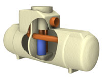
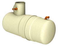
Full Retention Separator NS Range
Application
Full Retention Separators are used in high risk spillage areas such as: Fuel distribution depots, Vehicle workshops and Scrap Yards.
- Light and easy to install
- All surface water treated
- Used on high risk sites
- Sized in litres per second flow
- Available in Class I and Class II formats
- Class I designs includes coalescer and closure device, treating 100% of flow to achieve a concentration of 5mg/litre of oil
- Class II designs to achieve concentration of 100mg/litre of oil
- Independently tested and performance sampled, certified by the BSI
- Inclusive of silt storage volume
- Fitted inlet/outlet connectors
- Vent points within necks
- Extension access shafts for deep inverts
- Maintenance from ground level
What size Full Retention Separator do I need?
To specify a nominal size Full Retention Separator, the following information is needed:
- The calculated flow rate (NS) or the drainage area served. Our designs are based on the assumption that any interconnecting pipework fitted elsewhere on site does not impede flow into or out of the separator.
- The required discharge standard. This will decide whether a Class I or Class II unit is required
- The drain invert inlet depth
- Oil alarm system available
- Owls Hall offer a full Installation service. Please visit our Installation section for more information.
- Pipework type, size and orientation
Full Retention Separator NS Table
Sizes & Specifications
| Unit Nominal Size | Flow (l/s) | Drainage Area (m²) PPG3 (0.018) | Silt Storage Capacity Litres | Oil Storage Capacity Litres | Length | Unit Dia. | Access Shaft Dimensions | Base to Inlet | Base to Outlet Invert | Min. Inlet Invert | Standard Pipework Dia. |
|---|---|---|---|---|---|---|---|---|---|---|---|
| NS3 | 3 | 170 | 300 | 30 | 1760 | 1225 | 600 x 900 | 1050 | 1000 | 500 | 200 |
| NS6 | 6 | 335 | 600 | 60 | 1760 | 1225 | 600 x 900 | 1050 | 1000 | 500 | 200 |
| NS10 | 10 | 555 | 1000 | 100 | 2610 | 1225 | 600 x 900 | 1050 | 1000 | 500 | 200 |
| NS15 | 15 | 835 | 1500 | 150 | 3910 | 1225 | 600 x 900 | 1050 | 1000 | 500 | 200 |
| NS20 | 20 | 1115 | 2000 | 200 | 3200 | 2010 | 600 | 1850 | 1800 | 1000 | 200 |
| NS30 | 30 | 1670 | 3000 | 300 | 3915 | 2010 | 600 | 1850 | 1800 | 1000 | 315 |
| NS40 | 40 | 2225 | 4000 | 400 | 4360 | 2010 | 600 | 1850 | 1800 | 1000 | 315 |
| NS50 | 50 | 2780 | 5000 | 500 | 5425 | 2010 | 600 | 1810 | 1760 | 1000 | 315 |
| NS65 | 65 | 3610 | 6500 | 650 | 6850 | 2010 | 600 | 1810 | 1760 | 1000 | 315 |
| NS80 | 80 | 4445 | 8000 | 800 | 5700 | 2820 | 600 | 2500 | 2450 | 1000 | 315 |
| NS100 | 100 | 5560 | 10000 | 1000 | 6200 | 2820 | 600 | 2500 | 2450 | 1000 | 315 |
| NS125 | 125 | 6945 | 12500 | 1250 | 7365 | 2820 | 600 | 2500 | 2450 | 1000 | 450 |
| NS150 | 150 | 8335 | 15000 | 1500 | 8675 | 2820 | 600 | 2550 | 2450 | 1000 | 450 |
| NS175 | 175 | 9725 | 17500 | 1750 | 9975 | 2820 | 600 | 2550 | 2450 | 1000 | 450 |
| NS200 | 200 | 11110 | 20000 | 2000 | 11280 | 2820 | 600 | 2550 | 2450 | 1000 | 450 |
This Chart is a general guide
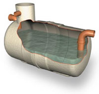
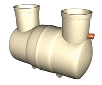
Washdown & Silt Separator
Application
This unit can be used in areas such as car wash and other cleaning facilities that discharge directly into a foul drain, which feeds to a municipal treatment facility. If emulsifiers are present the discharge must not be allowed to enter a NS Class I or Class II unit.
The main applications for the Washdown & Silt Separator are:
- Car wash
- Tool hire depots
- Truck cleansing
- Construction compounds cleansing points
- Light and easy to install
- Inclusive of silt storage volume
- Fitted inlet/outlet connectors
- Vent points within necks
- Extension access shafts for deep inverts
- Maintenance from ground level
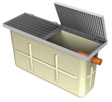
Silt Traps
- Designed for use before a separator in car wash applications to ensure effective
silt removal. - Galvanised heavy duty cover
- Light and easy to install
- Maintenance from ground level
Owls Hall offer a full Installation service. Please visit our Installation section for more information.
What size Washdown & Silt Separator do I need?
Washdown & Silt Separator Table
Sizes & Specifications
| Ref | Total Capacity (Litres) | Max. Rec. Silt | Max. Flow Rate (l/s) | Length | Diameter | Access Shaft Dia. | Base to Inlet Invert | Base to Outlet Invert | Standard Fall Across Unit | Min. Inlet Invert | Standard Pipe work Diameter | Approx Empty (Kg.) |
|---|---|---|---|---|---|---|---|---|---|---|---|---|
| W1/012 | 1200 | 600 | 3 | 1310 | 1225 | 460 | 1150 | 1100 | 50 | 500 | 160 | 60 |
| W1/020 | 2000 | 1000 | 5 | 2210 | 1225 | 460 | 1150 | 1100 | 50 | 500 | 160 | 120 |
| W1/030 | 3000 | 1500 | 8 | 3060 | 1225 | 460 | 1150 | 1100 | 50 | 500 | 160 | 150 |
| W1/040 | 4000 | 2000 | 11 | 3910 | 1225 | 460 | 1150 | 1100 | 50 | 500 | 160 | 180 |
| W1/060 | 6000 | 3000 | 16 | 4530 | 1440 | 600 | 1360 | 1360 | 50 | 500 | 160 | 320 |
| W1/080 | 8000 | 4000 | 22 | 3200 | 2020 | 600 | 2005 | 1955 | 50 | 500 | 160 | 585 |
| W1/100 | 10000 | 5000 | 27 | 3915 | 2020 | 600 | 2005 | 1955 | 50 | 500 | 160 | 680 |
| W1/120 | 12000 | 6000 | 33 | 4640 | 2020 | 600 | 2005 | 1955 | 50 | 500 | 160 | 770 |
| W1/150 | 15000 | 7500 | 41 | 5435 | 2075 | 600 | 1940 | 1890 | 50 | 500 | 160 | 965 |
| W1/190 | 19000 | 9500 | 52 | 6865 | 2075 | 600 | 1940 | 1890 | 50 | 500 | 160 | 1200 |
This Chart is a general guide
Grease Traps & Separators
Applications

Grease Traps: An effective and hygienic method of separating fat and grease from waste water flow.
Grease traps will, by the removal of fat and grease:
- Greatly reduce incidents of blocked drains from catering establishments
- Improve the performance of septic tanks and field drains
- Prevent contamination of small sewage treatment plants
Grease traps are designed for small restaurants, public houses and canteens.
Grease Separators: For applications such as larger restaurants, hotels, etc. where a grease separator should be considered to give additional volume.
Owls Hall offer a full Installation service. Please visit our Installation section for more information.
What size Grease Trap or Grease Separator do I need?
Grease Trap Table
| Trap Model No. | Grease Capacity | Dimensions | Weight Empty / Full (kgs) | ||
|---|---|---|---|---|---|
| A Length | B Length | C Length | |||
| 2 | 23 | 1330 | 850 | 1035 | 50 / 475 |
| 4 | 45 | 2070 | 1200 | 1335 | 120 / 1410 |
This Chart is a general guide
Grease Separator Table
| Separator Model | Dimensions | Working Capacity | Approx. Weight | Fall Across Unit | ||
|---|---|---|---|---|---|---|
| A | B | Empty | Full | |||
| G2B020 | 2210 | 1340 | 2000 litres | 100kg | 2200kg | 50 |
| G2B030 | 3060 | 2190 | 3000 litres | 130kg | 3180kg | 50 |
| G2B040 | 3910 | 3040 | 4000 litres | 160kg | 4160kg | 50 |
This Chart is a general guide
Forecourt Separator
Application
The forecourt separator is designed for installation in petrol filling station forecourts and similar applications. The function of the separator is to intercept hydrocarbon pollutants such as petroleum and oil and prevent their entry to the drainage system, thus protecting the environment against hydrocarbon contaminated surface water run-off and gross spillage.
- Light and easy to install
- Inclusive of silt storage volume
- Fitted inlet/outlet connectors
- Vent points within necks
- Extension access shafts for deep inverts
- Maintenance from ground level
- Class I and Class II design
- Oil storage volume
- Coalescer (Class I unit only)
- Automatic closure device
- Oil alarm system availble
Owls Hall offer a full Installation service. Please visit our Installation section for more information.
What size Forecourt Separator do I need?
Forecourt Separator Table
Sizes & Specifications
| Enviroceptor Class | Backfill Type | Total Cap. (L) | Drainage Area (m²) | Max. Flow Rate (l/s) | Length | Dia | Access Shaft Dia | Base to Inlet Invert | Base to Outlet Invert | Std. Fall Across Unit | Min. Inlet Invert | Std. Pipe-work | Empty weight (Kg.) |
|---|---|---|---|---|---|---|---|---|---|---|---|---|---|
| I | Concrete | 10000 | 720 | 15 | 3915 | 2020 | 600 | 2180 | 2130 | 50 | 600 | 160 | 620 |
| II | Concrete | 10000 | 720 | 15 | 3915 | 2020 | 600 | 2180 | 2130 | 50 | 600 | 160 | 620 |
This Chart is a general guide
The unit should be installed on a suitable concrete base slab and surrounded with a concrete backfill. Structural grade units can also be supplied suitable for installation within a granular backfill (i.e. pea gravel). Please specify unit required when ordering. If the separator is to be installed within a trafficked area, then a suitable cover slab must be designed to ensure that loads are not transmitted to the unit. The separator should be installed and vented in accordance with Health and Safety Guidance Note HS(G)41 for filling stations, subject to Local Authority requirements.
All Klargester products have a full initial 12 month warranty covering all mechanical and electrical components against malfunction, provided the unit has not been subject to damage or abuse.
Download Area
Which separator do I need?
Full Retention Separators
- Separators NSF3 – NS15 Class 1 & 2 Full Retention Installation, Operating & Maintenance Guidelines
- Separators NS20 – NS200 Class 1 & 2 Full Retention Installation, Operating & Maintenance Guidelines
- Pipework Orientations Diagram TDS0033-06
- Separators NS Class 1 & 2 FR NS3 – NS20 Specification TDS0031-05
Bypass Separators
- Bypass Separators NSB3 – NSB18 Installation, Operating & Maintenance Guidelines PD0313-07
- Bypass Separatosr NSB24 – NSB130 Installation, Operating & Maintenance Guidelines PD0314-03
- BP Separators NSB3 – NSB130 Class 1&2 Specification TDS0032-09
- Pipework Orientations Diagram TDS0033-06
Wash down Separators
- Wash Down & Silt Separators W1012 – W1190 Installation, Operation & Maintenance Guidelines PD0021-18
- Car Wash Silt Traps Installation Guidelines PD0072-03
- Car Wash Silt Trap Diagram 800341-06
- Washdown Separators W1012 – W1190 Specification TDS0037-03
Forecourt Separators
- Enviroceptors Forecourt Separators KZE – KZF10 Installation, Operating & Maintenance Guidelines PD107-10
- Enviroceptors Forecourt Separators Specification TDS0036-03
Grease Traps and Grease Separators


